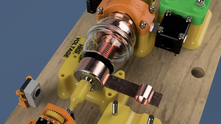
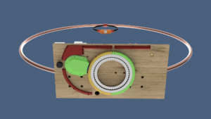
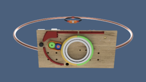
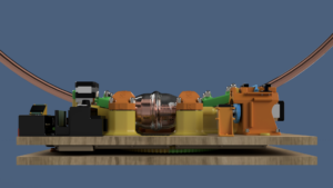
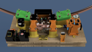
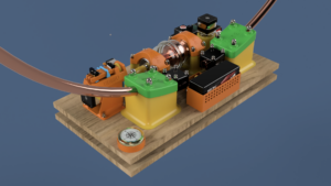
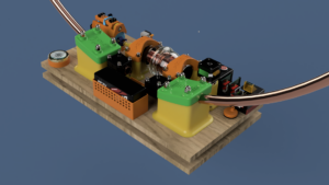
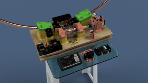
The entire project was centered around a vacuum capacitor acquired at the Hamfest in Friedrichshafen (Germany 2023).
An initial version of the design quickly revealed the necessity of incorporating a safety mechanism to prevent the stepper motor from exerting excessive force on the capacitor at its extreme positions.
The absence of such a system in the prototype led to potential risks of damage and operational instability.
Despite integrating a breakable shaft to mitigate these issues, frequent failures occurred during software debugging due to numerous application bugs. This highlighted the critical need for a more robust solution.
To address this, a failsafe mechanism was implemented to detect the capacitor’s limit positions and automatically cut off power to the stepper motors.
This hardwired solution, independent of the software, effectively prevents any damage to the capacitor and ensures smooth and reliable operation.
Vacuum Capacitor
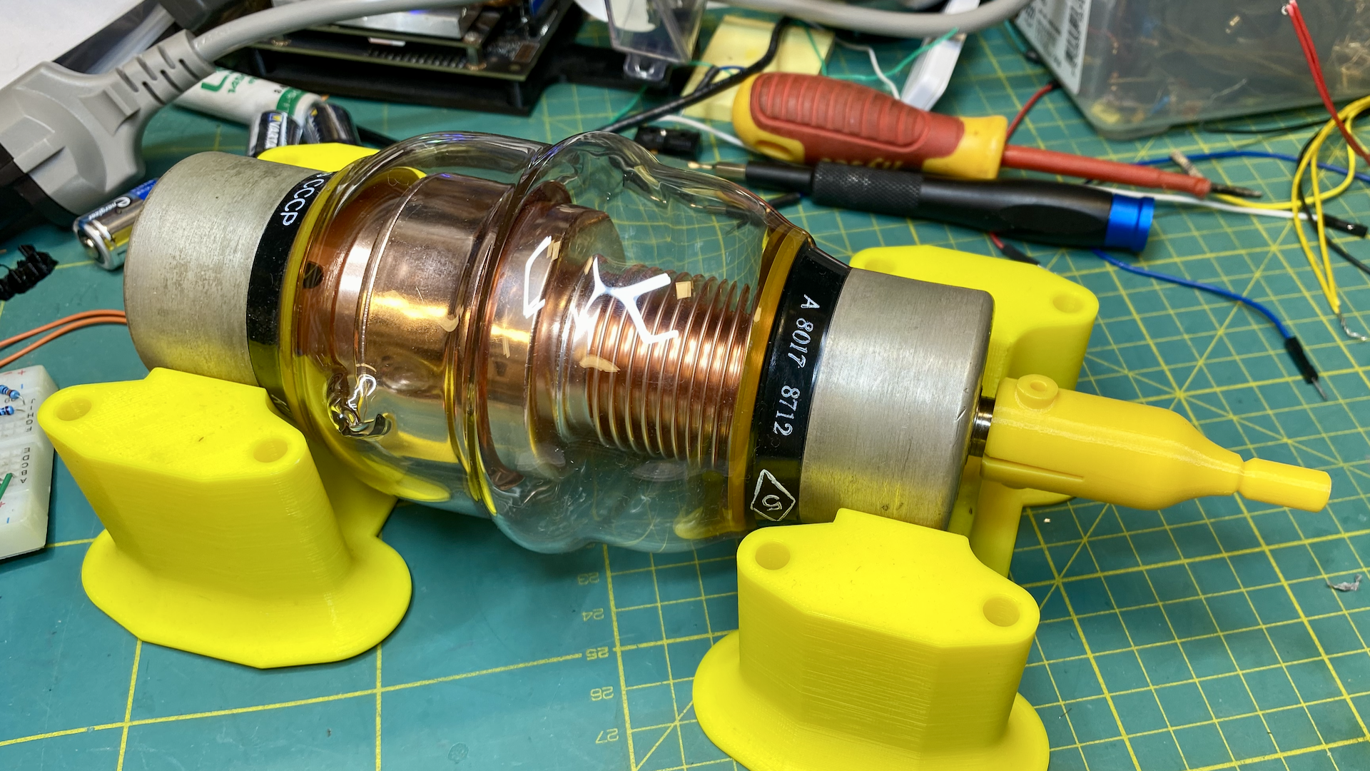
The vacuum capacitor is the core component of the antenna, providing the necessary tuning capability across a wide frequency range, specifically from 9 to 22 MHz in the case of the built antenna.
Vacuum capacitors offer significant advantages over air capacitors, including higher voltage handling, better stability, and lower loss.
These benefits result in more efficient performance and enhanced durability, especially in high-power applications.
Additionally, vacuum capacitors are not affected by weather conditions such as moisture, ensuring consistent performance regardless of the environment.
Loop
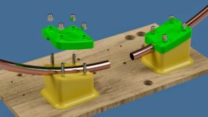
The loop was made from a 22mm copper pipe acquired in the form of a reel from a DIY shop.
Forming it into a 1.1-meter diameter was straightforward, thanks to a roller bending system equipped with 3D-printed rollers.
The connection between the loop and the vacuum capacitor terminals was established using copper strips and clamping blocks.
While it is acknowledged that this method may not be optimal due to potential resistive losses, which are crucial to avoid in magnetic loop antennas, it was chosen for its practicality in this prototype phase, and also because the writer’s soldering skills are not up to the mark.
Mounting Supports
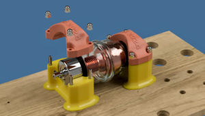
The loop and capacitor were mounted on 3D-printed sturdy saddles.
These custom-designed supports ensure precise alignment and secure attachment of the components, contributing to the overall stability and integrity of the antenna structure.
Stepper Motor Mounting
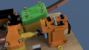
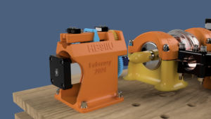
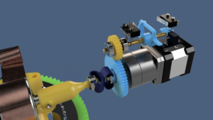
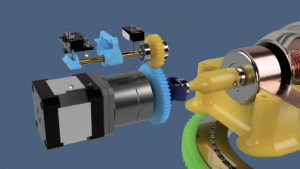
The stepper motor with reduction gear, responsible for adjusting the capacitor, was securely mounted onto the same support that integrates the aforementioned end limits safety system.
The connection to the capacitor is achieved by means of a flexible coupling to cope with small misalignments, ensuring smooth operation and reducing mechanical stress.
Failsafe Mechanism and Home Position Sensor
The two limit switches detect the end positions of the capacitor, and a small optical gate (optocoupler position switch) was included to detect the “home” position.
This ensures precise control and prevents any mechanical strain or damage, as the limit switches are hardwired and operate independently of software, ensuring reliable protection.
Coupling Loop Support
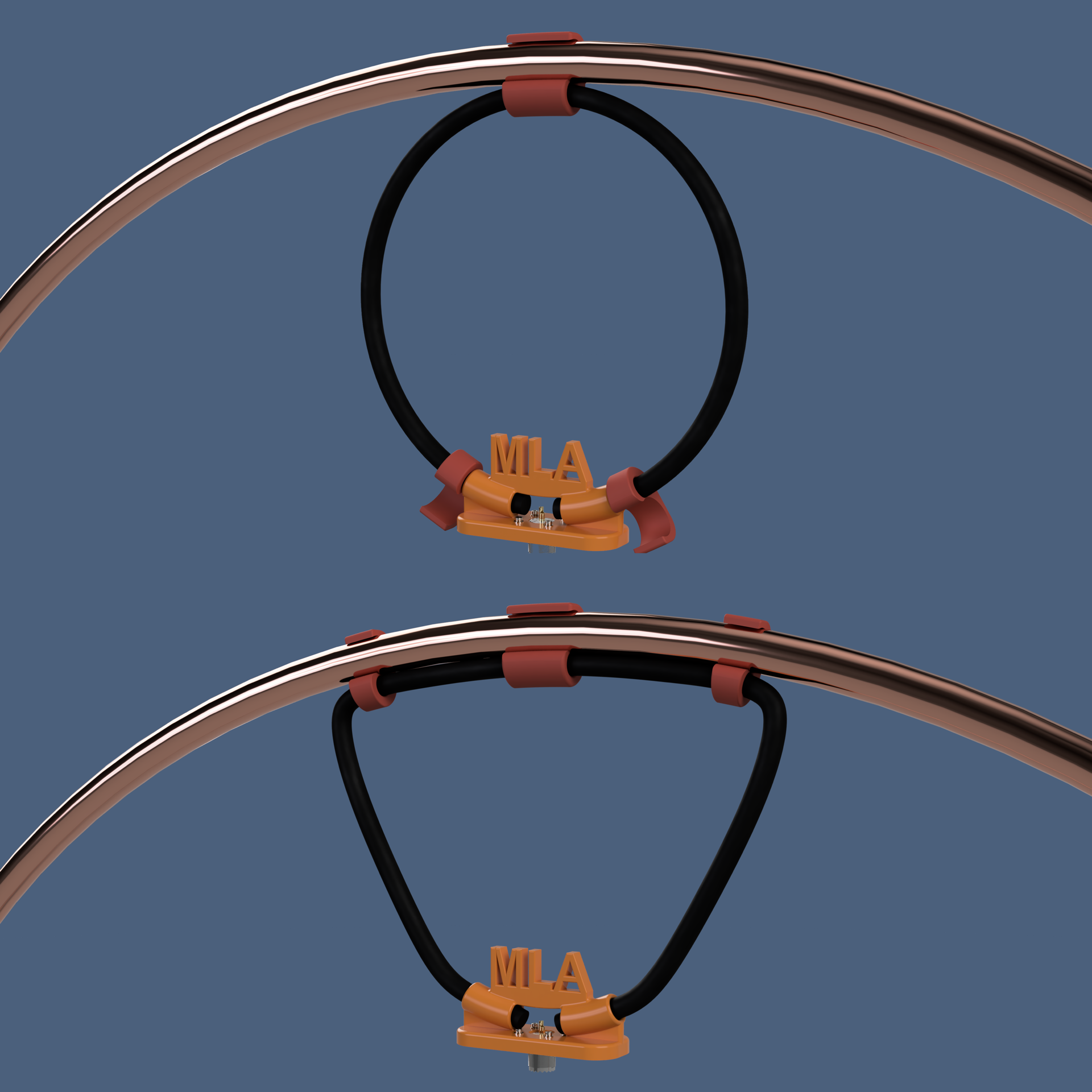
Different strategies can be employed to improve the SWR (Standing Wave Ratio) by matching the impedance of the feedline to that of the main loop in a magnetic loop antenna.
One suggested method involves rotating the coupling loop along the plane of the main loop.
However, based on personal experience, the most efficient approach is to manually squeeze the coupling loop using specially shaped supports, as shown in the picture below.
Antenna Azimuth Control
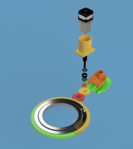
The azimuth control of the antenna (I like gadgets…) was achieved using a robust bearing typically found in rotating Chinese tables, often known as “lazy Susans.”
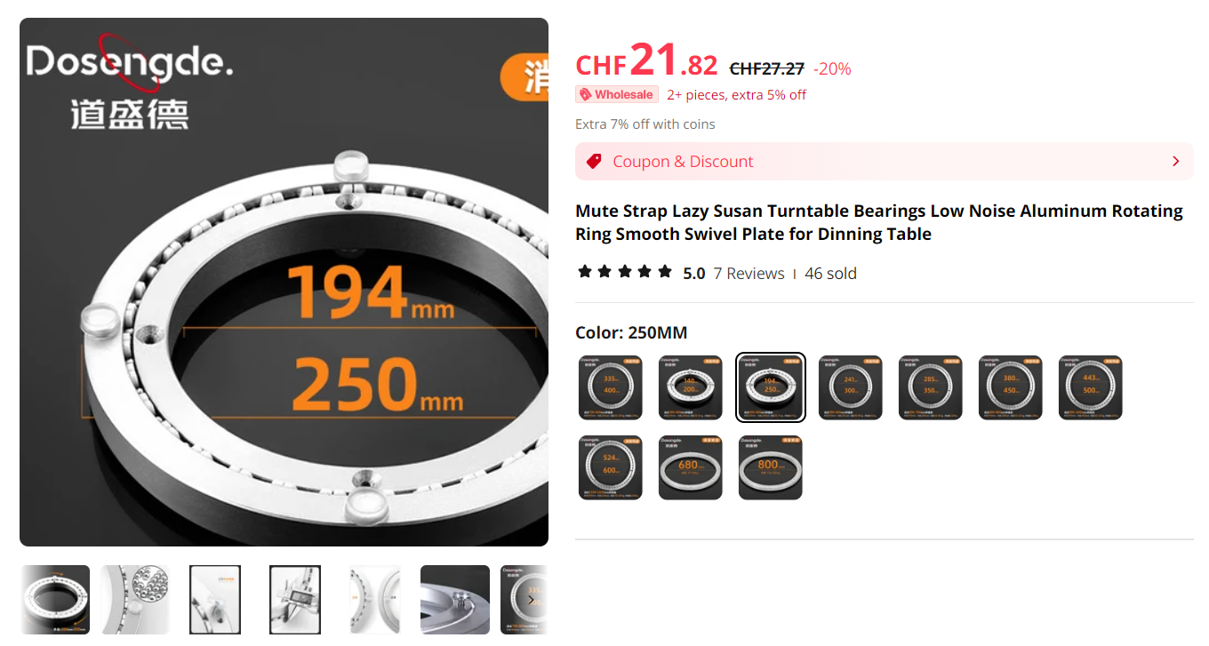
The rotation is transmitted through a set of 3D-printed gears driven by another stepper motor with a reducer.
The sophisticated design of the driving shaft ensures it won’t break if an obstacle stops the loop from rotating or if someone tries to position the antenna manually.
A small Hall effect sensor combined with a magnet is used to detect the home/parking position (North), ensuring precise orientation and control.
3D Design and Printing
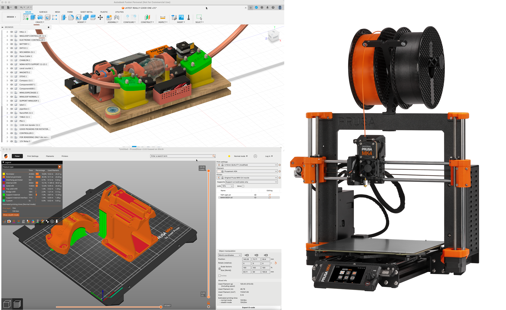
The 3D design and renderings shown here were created using Autodesk’s Fusion 360 (non-commercial use version).
All parts visible in the various renderings and the as-built pictures were printed on a Prusa MK3 printer, using PTFE and ASA materials.
Final Assembly
All components were carefully assembled, ensuring proper alignment and secure connections. The entire structure was tested thoroughly to verify its performance and reliability.
This iterative process of design, testing, and improvement was essential in creating a robust and efficient magnetic loop antenna.
However, it is evident that the antenna was not designed for outdoor installation, which is not an issue as it is intended to be located in the attic.
The lessons learned from the initial build were invaluable in refining the final product.


