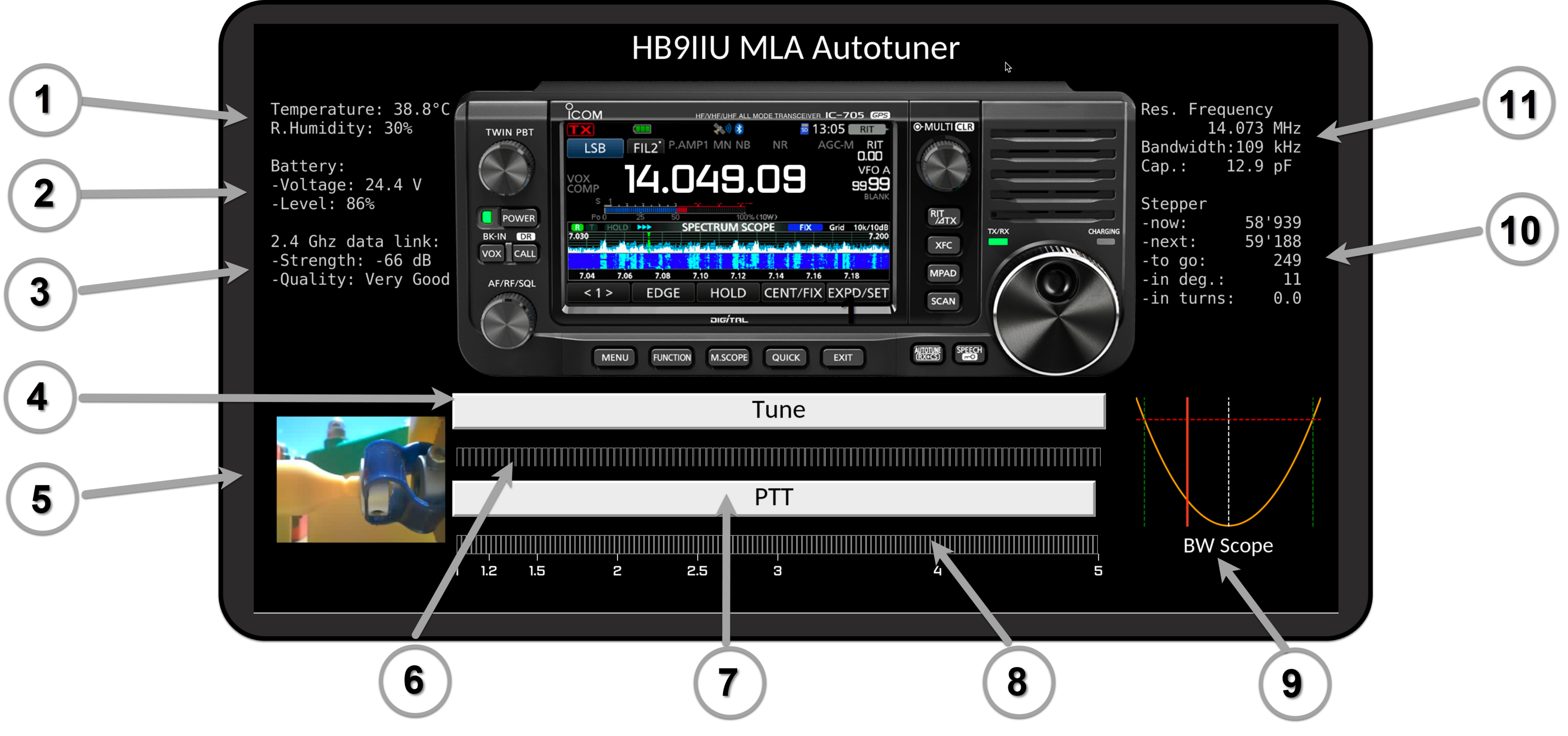
This screen was designed to monitor and control the semi-automatic tuning of the antenna.
It features a virtual Icom IC 705, providing live updates of the set VFO frequency synchronized using the CAT protocol via Bluetooth.

1. Temperature & Humidity
Current temperature and humidity levels recorded by the onboard DHT22 sensor.
Note that the unusually high displayed temperature is because the unit was placed directly under the sun.
2. Battery Status
This section displays the current battery voltage and charge level.
Battery voltage is acquired via an ADC input of the ESP32.
The system is equipped with a device that will cut off the battery at a specific voltage level to avoid total discharge and potential damage.
3. Link status
This section indicates the quality of the 2.4 GHz communication link between the Raspberry Pi and the onboard ESP32 microcontroller.
Data transfer between the ESP32 and the Raspberry Pi is done via UDP datagrams using the AsyncUDP library.
4. PTT Button
Pressing this button causes the IC 705 to generate a low-power continuous carrier to check the SWR.
When pressed, the mode automatically changes to FM and reverts back to the originally set operating mode when released.
5. Live View of Capacitor Drive
This gadget provides a live view of the stepper-capacitor flexible coupling. The feed is captured by the mini M5 Stack cam.
6. Stepper Movement Progress Bar
Bars showing the displacement progress of the stepper motor when moving to a new position.
7. PTT Button
Pressing this button initiates a re-tuning to achieve the best antenna performance at the currently set VFO frequency.
8. SWR Meter
This bar graph displays the live SWR (Standing Wave Ratio) returned by the IC 705 during tuning or transmitting.
9. Bandwith Scope
This is probably the most interesting feature. It shows where we stand (represented by a red line) within the operable frequency range where SWR is predicted to stay below 3. The parabolic representation is not the result of a sweep, but provides an indication of when re-tuning is required, with the red line dynamically indicating the current frequency
10. Next Tuning Info
This section provides information on potential stepper motor movements required for re-tuning to achieve optimal performance, ensuring the red line in the bandwidth scope is centered.
11. General Info
This section is included to fully utilize and balance the screen. It provides the current resonance frequency, extrapolated capacitor value, and predicted bandwidth.
