Impact of Stepper Motor Movements
During the initial stepper motor trials, one of the most striking observations was the profound impact of even minor adjustments in stepper motor movements.
It was astonishing to see how just a few steps of rotation could cause noticeable shifts in the antenna’s resonance frequency.
This sensitivity highlights the high Q value (quality factor) of the antenna, indicating that achieving precise tuning manually would be exceedingly challenging.
I am particularly pleased with the choice of a stepper motor with a reducer and the discovery that my stepper drivers support microstepping.
These features have been instrumental in achieving the required fine control.
Some might say it’s over-engineered, but as a Swiss native from the land of watchmakers with a background in fine mechanics engineering, I have a deep appreciation for precision. After all, why settle for anything less when you can achieve Swiss-watch-level precision in antenna tuning?
In fact, when coding the system, I even managed the geared motor backlash to further refine control over antenna tuning
Loop Diameter
However, to enhance versatility and optimize performance for specific frequency bands, I plan to reduce the diameter of the loop.
My current loop antenna has a diameter of 1.1 meters and can be tuned within a frequency range of 9.7 to 22.5 MHz.
This adjustment aims to tentatively cover the range from 20 meters to 10 meters.
Power Supply to the Raspberry PI
While developing the code on the Raspberry Pi, it was powered by the original Raspberry Pi 5V/2.5A wall socket power supply, and everything worked perfectly.
However, after wiring the Pi and connecting it to a dedicated external supply capable of delivering more than 5A, I started receiving annoying undervoltage warnings on the display, and my VNA would disconnect three seconds after successfully connecting.
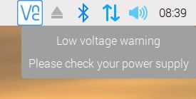
After extensive troubleshooting, I discovered that although my lab PSU was set to 5V, only 4.6 volts were measured at the pins on the Pi. This was due to voltage drop in the feeding line, as the entire controller, along with the display, was drawing approximately 1.5A. To avoid these voltage drops, I used larger wires to supply power to the Pi.
I wanted to highlight this issue because I have seen many forum posts from people facing the same problem and not understanding why, despite measuring 5V at the source, they still receive this undervoltage message.
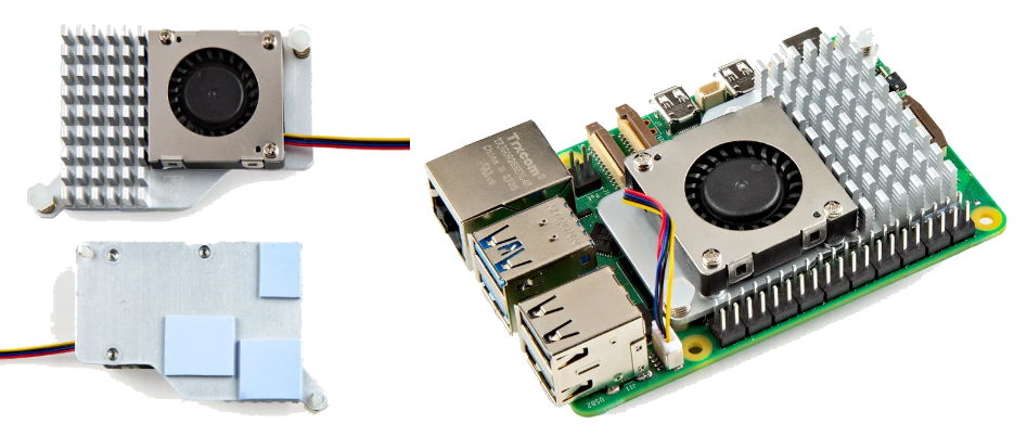
Cooling of the Raspberry PI
The discovery of this relatively high current draw of 1.5A explained the high CPU temperatures displayed in my app on the system info page, sometimes reaching close to 100°C.
The main power consumer in the controller is actually the display, and since the entire setup, along with the Pi, is installed in a compact enclosure, heat dissipation is challenging.
Consequently, I searched for a cooling solution and found a nice little Pi add-on that I managed to install without having to redesign the enclosure. The reported CPU temperature now never exceeds 45°C, which is obviously a much better outcome.