Introduction
I have always been fascinated by Magnetic Loop Antennas. While I’m not a fanatical radio ham (I only go on air occasionally and for short periods—I’m not really into contests but rather enjoy technical discussions, which are becoming increasingly rare), what truly captivates me is the challenge of tuning these antennas, especially due to their very high Q factor.
For those not familiar with the term, “high Q” refers to the quality of the antenna’s resonance. A high-Q antenna means it has a very narrow bandwidth, which makes it more sensitive to small changes in frequency. This requires precise tuning, which is both challenging and rewarding. The higher the Q, the more critical it is to fine-tune the antenna for optimal performance.
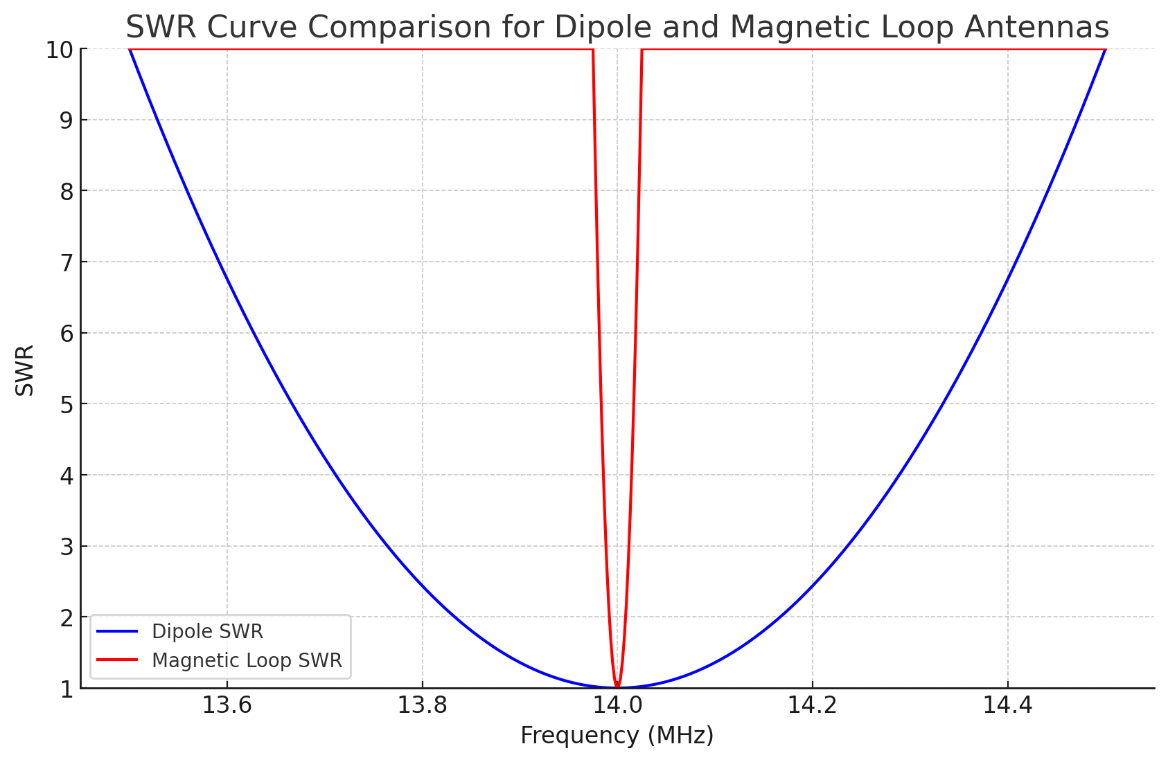
Here’s the SWR curve comparison for a dipole and a magnetic loop antenna:
- Dipole Antenna (Blue Curve): The broader SWR curve shows that the dipole has a wider bandwidth, with a lower SWR over a larger frequency range. This makes it easier to tune and less sensitive to slight frequency shifts.
- Magnetic Loop Antenna (Red Curve): The narrow SWR curve demonstrates the high-Q characteristic of the magnetic loop. It has a very narrow bandwidth around the center frequency of 14 MHz, which means that even a small deviation from this frequency results in a higher SWR.
SWR curves, assuming an ideal resonance at 14 MHz for both, with different bandwidths to reflect the Q differences between the two antennas.
4o

aaaaa
Project Overview
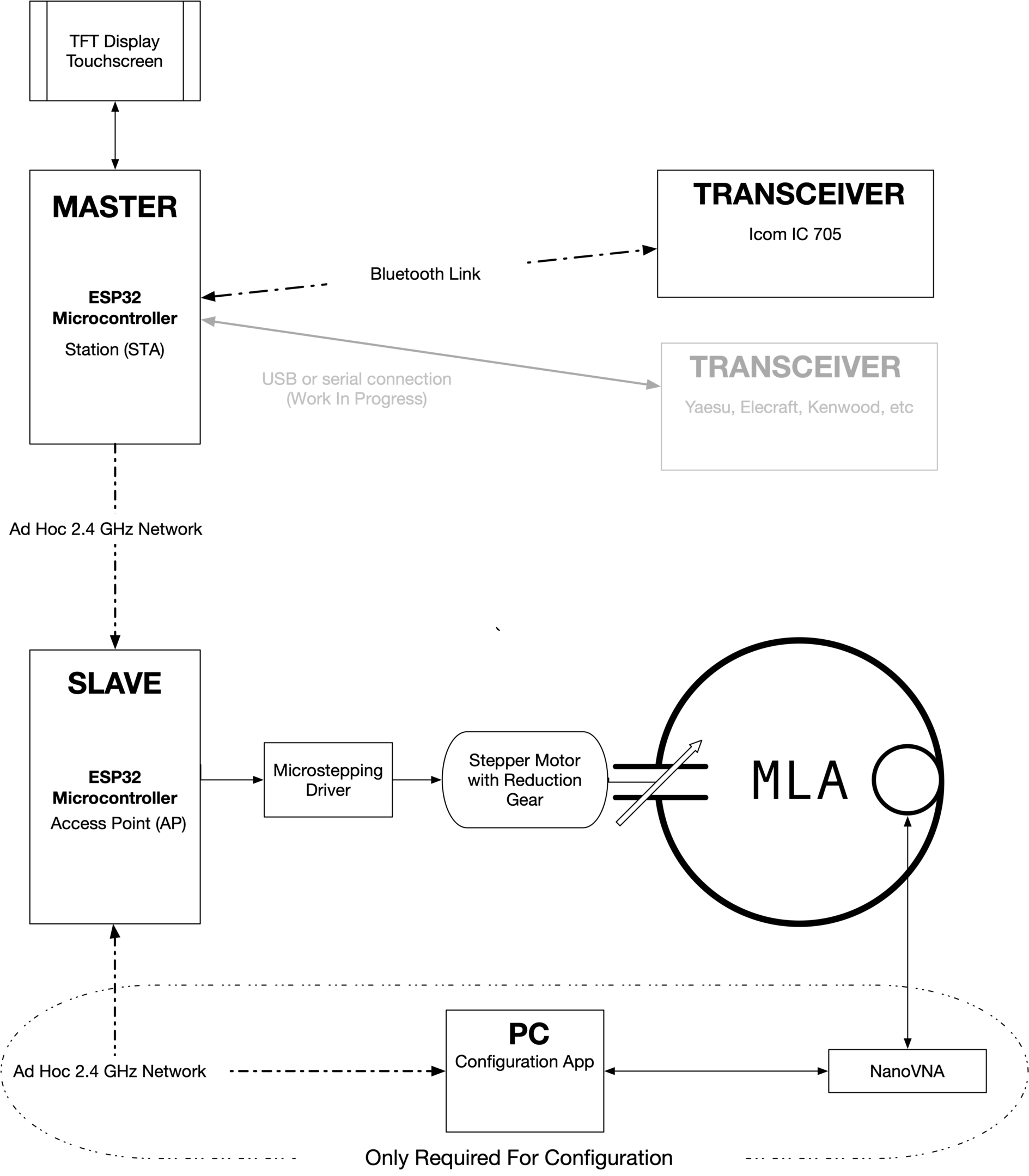
This project is a fully automated tuning system for a Magnetic Loop Antenna (MLA), designed to simplify and enhance the tuning experience, especially for high-Q antennas. The setup consists of a “Master” ESP32 microcontroller that serves as the main controller, paired with a “Slave” ESP32 that manages the motor controlling the antenna’s tuning capacitor.
Here’s how it works:
- Master ESP32 with TFT Display: The Master ESP32, equipped with a TFT touchscreen display, serves as the primary interface for the user. It retrieves the VFO (Variable Frequency Oscillator) frequency from an Icom IC-705 transceiver via a Bluetooth connection, allowing for automatic adjustments based on the transceiver’s operating frequency. For other transceiver models (such as Yaesu, Elecraft, Kenwood), a USB or serial connection is planned.
- 2.4 GHz Network Communication: The Master ESP32 communicates wirelessly with the Slave ESP32 over an ad hoc 2.4 GHz network. This approach was chosen specifically to avoid reliance on a router, making the setup ideal for field operations where access to network infrastructure may be limited.
- Slave ESP32 with Stepper Motor Control: The Slave ESP32 controls a stepper motor (via a microstepping driver) connected to the MLA’s tuning capacitor. The stepper motor, equipped with a reduction gear for precision, adjusts the capacitor to achieve the desired resonance frequency based on instructions from the Master ESP32.
- PC Connection for Initial Configuration: A PC with a configuration app is required for the initial setup to generate frequency/stepper position lookup tables, which are essential for precise tuning. This calibration process, typically performed with a NanoVNA, allows the system to map resonance points accurately. Once configured, the system can operate independently without a PC, making it well-suited for portable and standalone use.

blabla
Operation
When powered on, the Master Controller automatically connects to both the Slave ESP32 and the IC-705 radio. From the radio, it retrieves the current VFO frequency, and from the Slave, it gets the current capacitor position in steps, stored persistently in flash memory. This ensures that the system resumes operation quickly and accurately, even after being powered off.
After receiving the VFO frequency from the IC-705, the Master instructs the Slave to consult a lookup table (containing 5000 entries for the 20m and 40m bands, respectively). The Slave then calculates the theoretical resonance frequency and determines the number of steps needed to adjust the capacitor to match the VFO frequency. This information, including the target resonance frequency and step count, is displayed on the Master’s TFT screen, giving the user a real-time view of the tuning adjustments.
Since the TFT is a touchscreen, the user can simply tap the screen to initiate the tuning process. Once tuning begins, a progress bar appears on the display, indicating that the stepper motor is in motion. This bar graph provides real-time feedback on the progress, showing the adjustment as the capacitor moves toward the target position for optimal resonance.
With another tap on the touchscreen, the user can display an SWR meter. To measure the SWR, the transceiver is briefly set to FM mode to produce a steady carrier, with the power reduced to a minimum. The system engages the PTT (Push-to-Talk) for a couple of seconds, during which the IC-705 provides SWR information via the CAT protocol—no external SWR meter is needed. This allows the user to quickly verify the antenna’s tuning and get confirmation of correct tuning. No further adjustments are required. After the measurement, the transceiver is automatically returned to its initial mode and power settings.
Additional Features
The TFT display includes a small widget that shows the quality of the 2.4 GHz link between the Master and Slave ESP32s, providing a quick visual indication of signal strength and connection stability.
Since there was extra space on the display, I also added “WSPR” and “FT8” buttons for convenience. With a simple tap, these buttons quickly tune the transceiver to the relevant frequency for WSPR or FT8, allowing the user to observe signals on the IC-705’s waterfall display as a quick check of band activity.
Additionally, there’s a ‘Set’ button that brings up a virtual keyboard for frequency entry. This feature allows the user to “re-center” the lookup table if any changes have been made to the drive mechanism. By connecting a VNA, finding the resonance dip, and entering the frequency via the virtual keypad, the Slave can recalibrate and accurately identify the capacitor’s position. This ensures precise tuning and alignment with the lookup table.
Initial Configuration
Since the system operates based on a lookup table, it’s necessary to create one initially. This could theoretically be done manually by noting down resonance frequencies for different capacitor/stepper positions. However, I wanted a fully automated solution, so I developed a Python app that controls a low-cost Chinese VNA and the Slave ESP32 to manage the stepper motor.
Here’s how the system automatically generates the lookup table:
- Positioning the Capacitor: The capacitor is initially set to the beginning of the 20m or 40m band.
- Data Collection: The VNA automatically retrieves S11 data and applies a calibration network for accurate measurements.
- Stepper Adjustment: The stepper motor advances a few steps forward.
- Data Logging in a Loop: Steps 2 and 3 repeat in a loop, progressively moving across the band and collecting resonance data.
The entire process and its progress are visualized on a feature-rich webpage. Once the data collection is complete, the webpage allows testing of the system’s accuracy, ensuring the lookup table is correctly aligned with actual resonance points.
After gathering all measurements, the system generates a lookup table with 5000 interpolated data points per band. This table is then uploaded to the Slave ESP32 and stored in its flash memory, providing the precise resonance positions needed for automatic tuning. Importantly, this calibration process is only required once. I completed the setup a month ago and still achieve excellent positioning accuracy. However, the calibration may need to be revisited if using an air capacitor, as climatic conditions can affect its capacitance and, consequently, the tuning stability.
Open Source
If you’re interested, you can build your own system—everything is open source and available on GitHub. This is actually my first time using GitHub, so this project has also been a great opportunity to learn something new.
That said, I have limited time available, so I may not be able to provide quick fixes or improvements on the fly. I appreciate your understanding and hope you find the project useful!
Final Thoughts
I have to admit, I’m extremely happy with the end result of this project. It’s amazing to see how precisely the system can tune the antenna. As a mechanical engineer, I’m familiar with the concept of backlash, but it took me a while to realize that it needed to be addressed here as well.
For those unfamiliar, “backlash” refers to the small amount of play or slippage that occurs in mechanical systems, especially when reversing direction. In a stepper motor setup like this one, backlash can lead to slight inaccuracies if not compensated. To solve this, I included a backlash compensation algorithm in the code, ensuring that the tuning remains precise regardless of direction changes.
This project also helped me deepen my understanding of ESP32 coding, particularly in developing GUIs for the TFT touchscreen. Overall, I’m thrilled with how it turned out and am already looking forward to my next challenge.
If you have a project idea in mind and aren’t sure where to start, feel free to reach out—I’d be glad to help brainstorm or provide some guidance!
